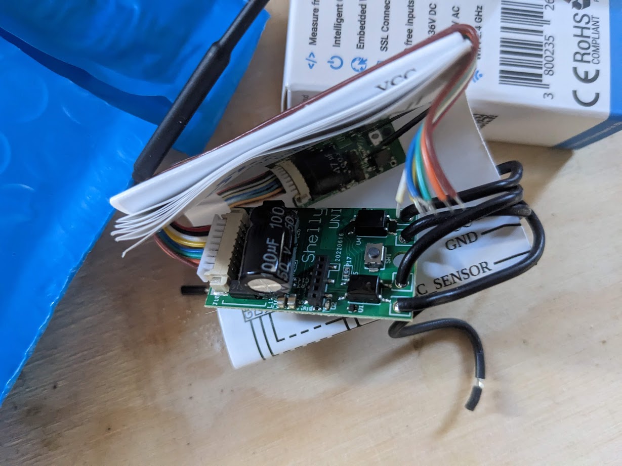
In 2023, I managed to integrate my garage doors with HomeAssistant using a Shelly Uni device. Controlled remote operation is pretty great, but I wanted to document this project because this solution covers remote door control, door state and even door light control is possible, using a single $12 device with no batteries required. The setup is easy to achieve, and leaves all the garage door opener functionality in tact.
Overview
- Shelly Uni device is powered from a 12v DC power source leeched from the low-voltage side of the garage door control circuit board
- Garage door switch is operated using one of the two potential free outputs on the Shelly Uni
- Garage door state is monitored using both Shelly Uni inputs, detecting open/closed circuits on the garage door opener’s own state sensors
- Light control is not implemented, but could be added to the extra Shelly Uni output in an extremely simple circuit
Shelly Uni
I found the this product after having played with a few other devices in the Shelly ecosystem. These devices are excellent. They are easy to set up via captive WiFi portal. They of course join your WiFi network. They can be controlled locally with no cloud services via their own built-in web servers, HomeAssistant, or other local message systems. I have nothing but good things to say about my experience with these devices.
The Uni in particular is well suited for garage door control and state monitoring because of its flexible power input specifications (AC 12V – 24V or DC 12V – 36V), because it can be configured as a momentary switch just like the physical garage door wall-mount button, and has those two inputs which are perfect for observing state which I will get into later.
Getting the Cover Off
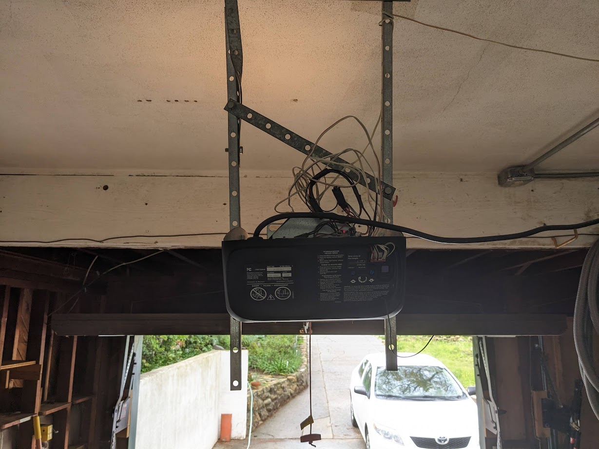
One of the trickiest parts of this garage door opener modification was getting the case off. I’m not garage door service pro, so figuring out how to get this case removed was a slow process. Maybe this is easier if you remove the whole unit from the ceiling, but I didn’t want to do that. In the end, I did manage to get the cover off the unit without breaking anything and without the use of a grinder.
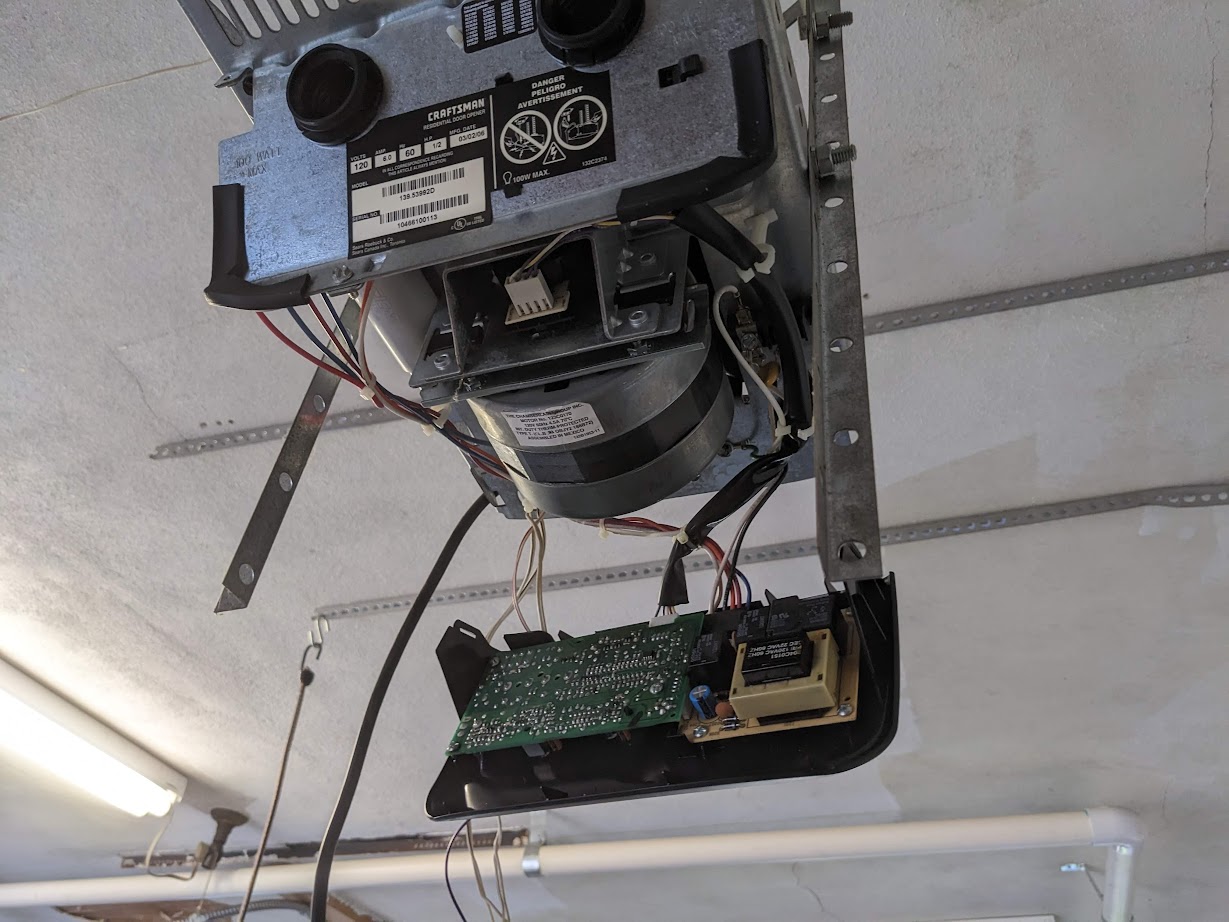
With the cover off and the unit safely unplugged, I was able to get a good look at the internals. The bulk of it is obviously the large drive motor, but there are also two circuit boards in the back. You can see the mains voltage connected directly to the smaller brown board, and power leads for the motor and lights leading out.
Power Source
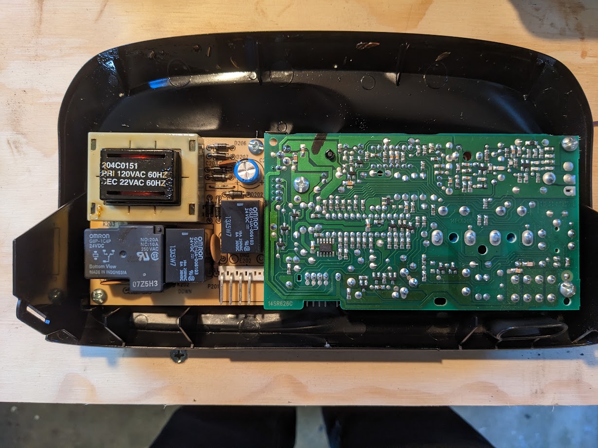
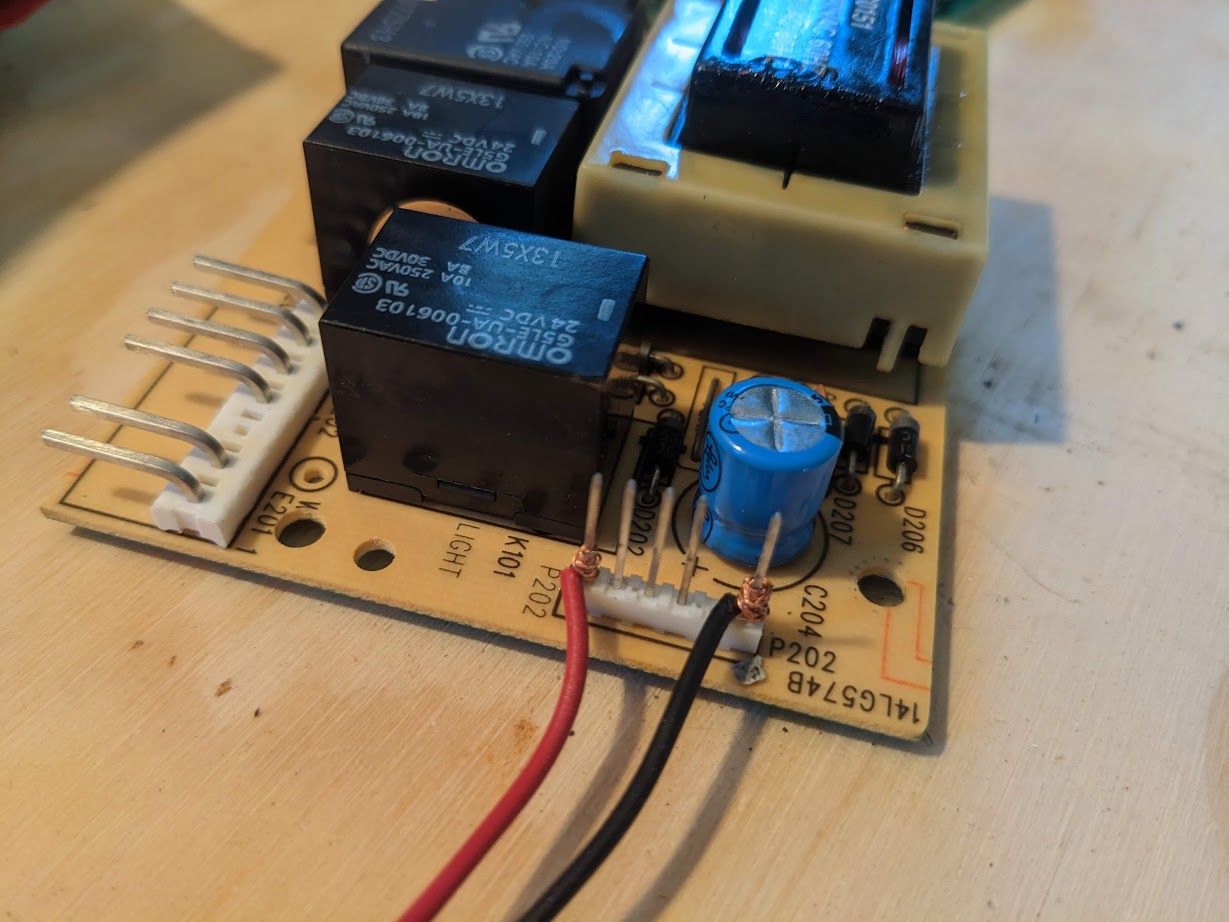
My first order of business was to get these circuit boards off the ceiling and onto the bench for a closer inspection. My plan was to find a suitable power source somewhere on one of these boards, and assume that the load of the tiny device wouldn’t even be noticed. One very easy source appeared to be the step-down transformer which was clearly labeled 22VAC, well within the documented input range of the device. But when I measured the actual potential it was out of range at 28VAC. But on the low voltage side, I found a nice 12VDC right on the connection between the two boards.
I did not feel like soldering directly to the circuit board, so I wrapped the posts of the connector with some solid copper wire before plugging the boards back together and re-assembling.
Door State
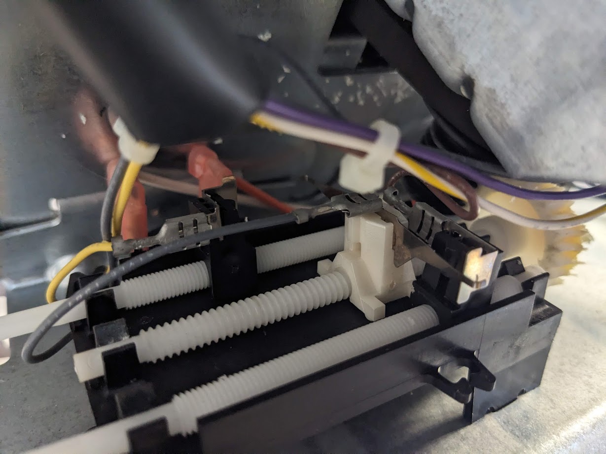
The garage door opener unit itself needs to be able to detect when the door is fully opened or fully closed so it can stop the motor. To do this, my unit has a very simple, ingenious, and adjustable mechanism. Through a series of nylon gears, the movement of the door causes a grounded carriage (connected to the gray wire) at the front of the machine to traverse the space between two separate +5V (yellow and brown wire) contacts.
So the potential measured between the yellow and gray wires is 0 when the door is fully open and +5V when not fully open. The potential between the brown and gray wires is 0 when the door is fully closed and +5V when the door not fully closed. So with these three contacts, and the two inputs on the device, we can know when the door is fully open, when it is fully closed and when it is neither.
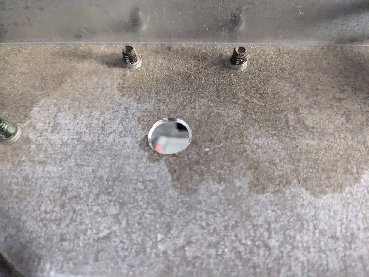
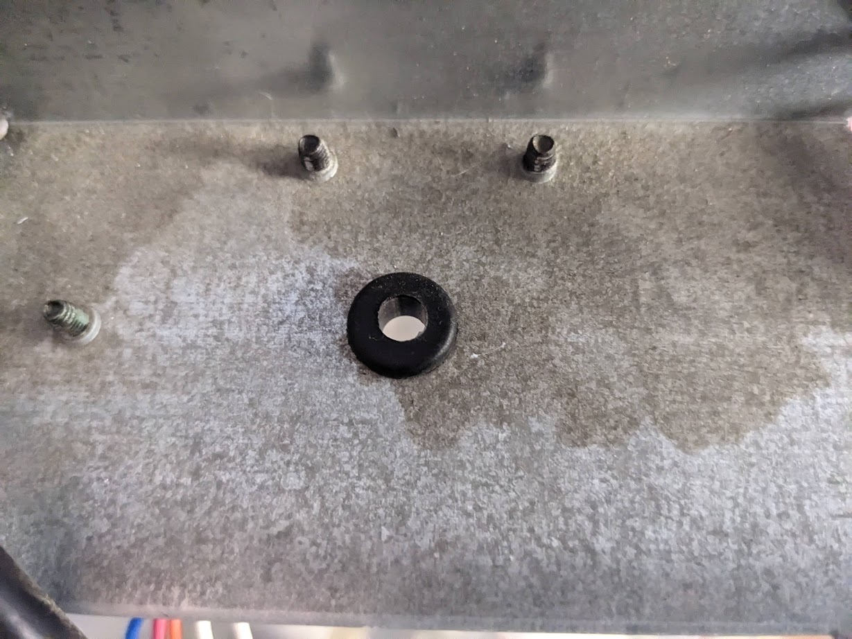
All that was left was to wire it up and find a place for the device to live. I wasn’t sure about packing it all into the metal garage door casing. In hindsight, I probably could have managed it and it would have looked nicer. But I wound up drilling a hole in the case and routing the cables through a rubber grommet on top.
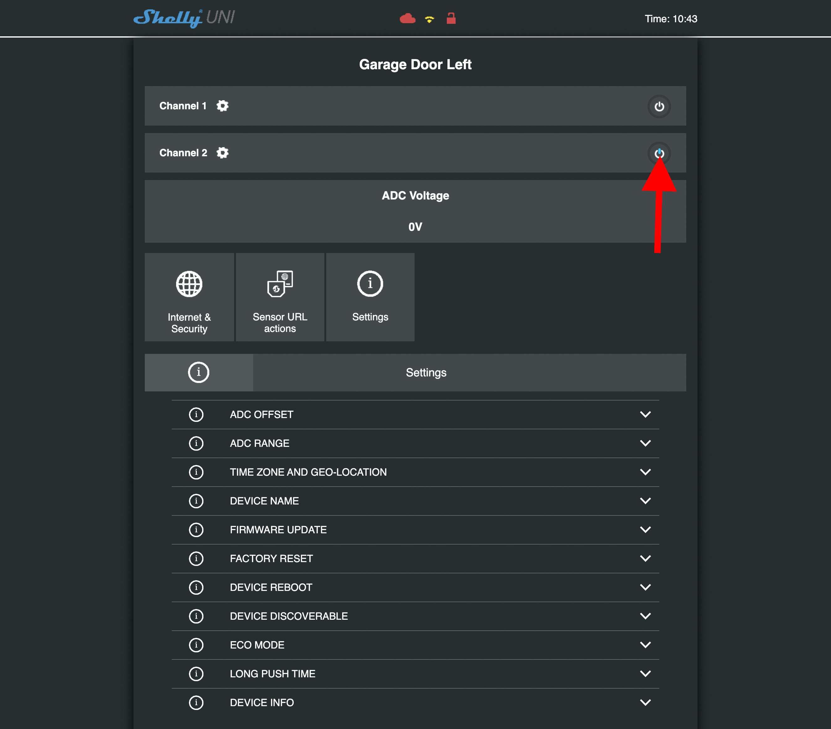
Door state information appears in this very tiny blue indicator in the UI.
It has been over a year now and this setup has been working great on both my garage door openers. I have it integrated with HomeAssistant which makes for very convenient remote operation. At one point, wall-mounted button was sticking and I believe the stuck button somehow triggered a factory reset of the Shelly device. But I did clean that plastic switch and lubricated it with mineral oil and it hasn’t had a problem since.
HomeAssistant Configuration
You don’t need to use HomeAssistant to make use of this setup, but it is quite nice. In HomeAssistant, garage doors can use the ‘cover’ template and my configuration looks like this:
cover:
  - platform: template
    covers:
      garage_door_right:
        device_class: garage
        friendly_name: "Garage Door - Right"
        unique_id: garage_door_right
        position_template: >-
          {% if (is_state('binary_sensor.garage_door_right_channel_1_input','on') and is_state('binary_sensor.garage_door_right_channel_2_input','on')) %}
            {{50|int}}
          {% elif is_state('binary_sensor.garage_door_right_channel_1_input','on') %}
            {{0|int}}
          {% elif is_state('binary_sensor.garage_door_right_channel_2_input','on') %}
            {{100|int}}
          {% endif %}
        open_cover:
          service: switch.turn_on
          data:
            entity_id: switch.garage_door_right_channel_2
        close_cover:
          service: switch.turn_on
          data:
            entity_id: switch.garage_door_right_channel_2
