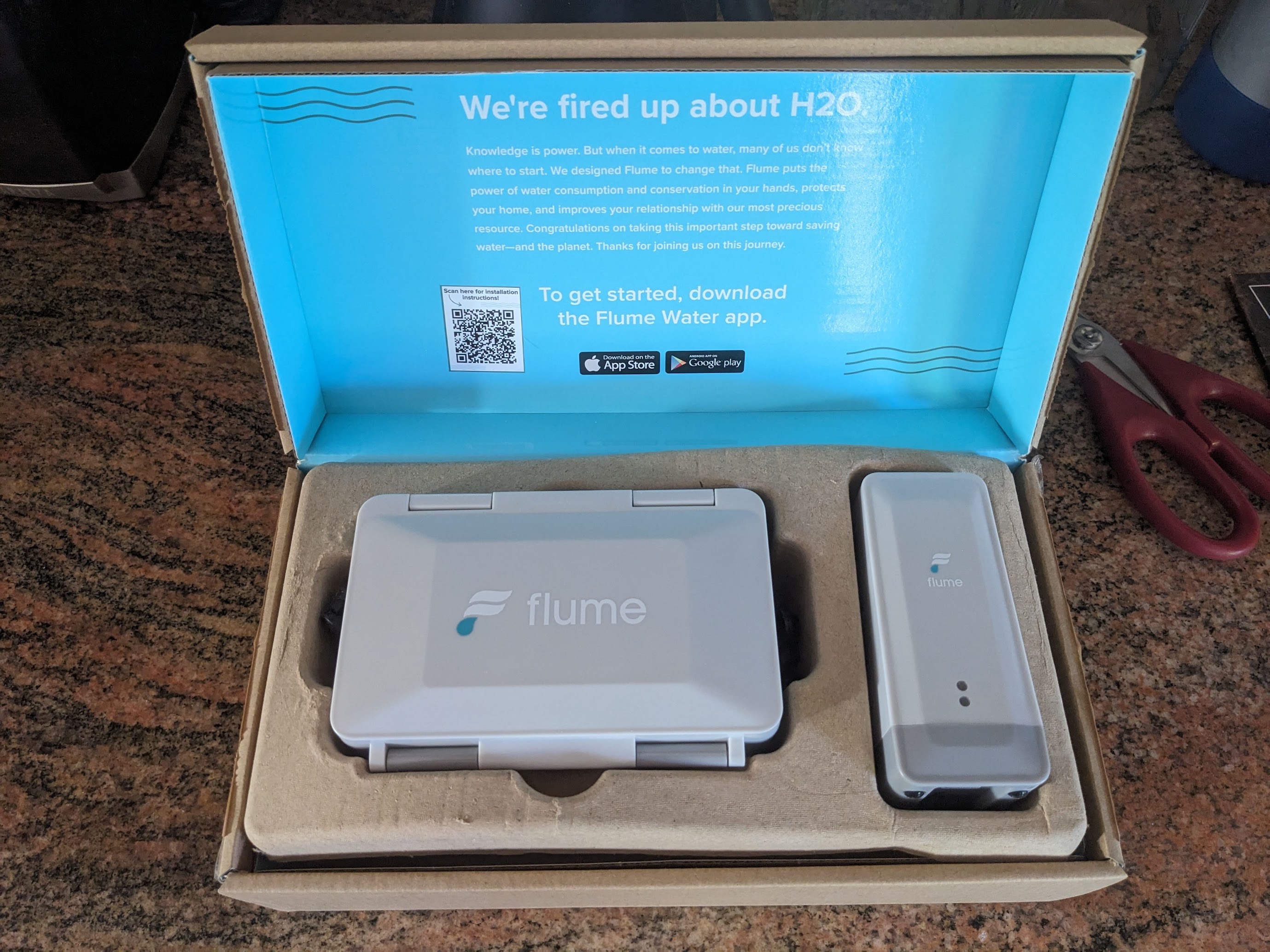
About a year ago, I bought a smart home water monitor in order to keep an eye my water use at home. The city where I live provides a big rebate on one particular device from San Luis Obispo company Flume. I was immediately curious about how this device could work and was excited to open the box when it arrived and inspect the contents.
There are two hardware components in this system. One component, the sensor, is designed to be physically strapped to your water meter. The other component, the bridge, receives information from the sensor and connects to the Internet via Wi-Fi to deliver all this data to Flume. Flume provides an API for customers to access their own data and there’s even a Home Assistant plugin which should help bring all this information to the platform I run at home.
But I wanted to learn more about how this all works and was curious if there could be a way to access this data more directly. As friendly as Flume seems to be, I do feel that if I buy a device to track my own data, that data should belong to me. But also, it would be nice to know that if Flume ever closes up shop or shuts down its web service, that these devices could all still be useful. So let’s take a closer look at the hardware to see what’s really happening.
The Sensor
In order to function, the sensor has to be physically adjacent to the water meter. In many cases, that means outside. So the hardware lives in a well-sealed plastic enclosure with a nice rubber O-Ring to hopefully keep the water out. Inside the enclosure, there is room for two battery packs. Although, only one is provided. They say one battery pack will last a year, but mine has been running for over a year and is still working fine. Battery power makes sense because water meters don’t always have power available nearby. Plus, keeping batteries inside the enclosure means no holes in the enclosure are required and hopefully less chance of water getting in. It would be nice if flume would offer a wireless power option. Something built from a cheap 5v wireless charging circuit should be a nice fit, and maybe I’ll do that at some point if I ever get tired of replacing batteries.
So the sensor has to continually monitor water use for at least one year, using only a small battery pack and wirelessly transmit all that water use data to a receiver. Let’s look at the sensor more closely to see how it works.
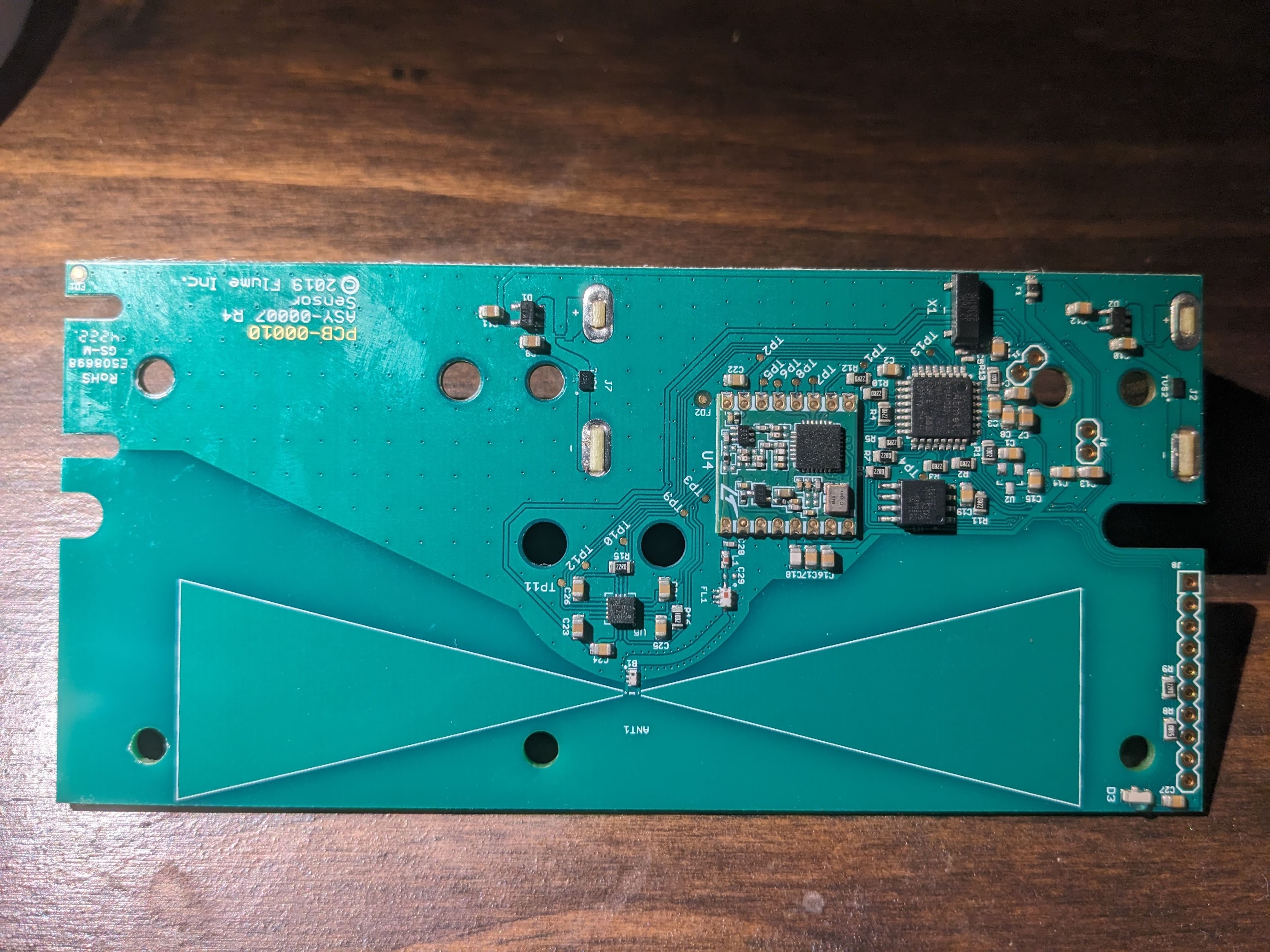
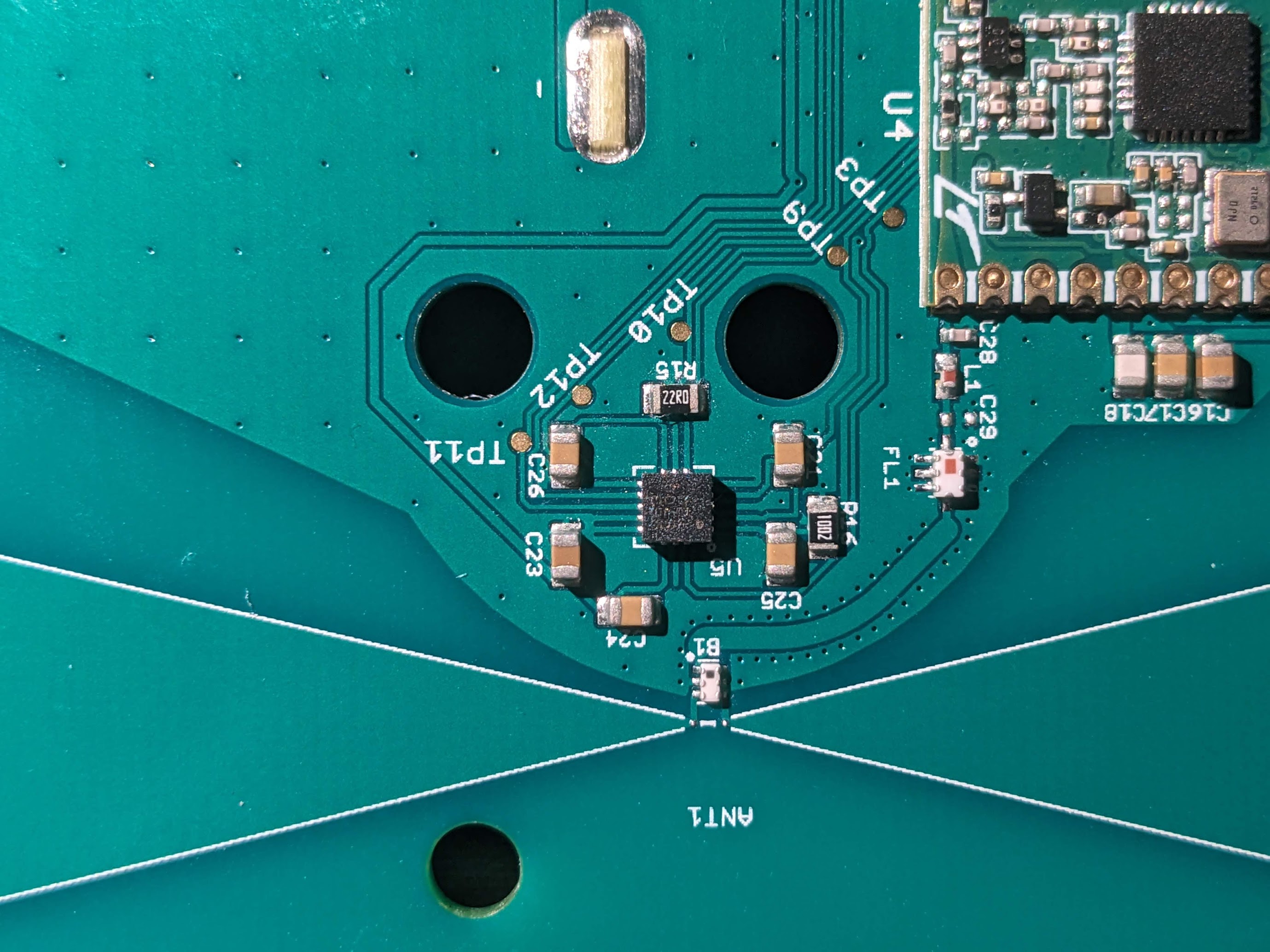
Clearly the sensor has a big bow-tie antenna printed onto its circuit board. This seems to be a popular choice for sensor network applications. Close to the center of the board we see some kind of sensor. The markings on the IC package are hard to read, but based on some research into how this kind of device works, it must be some kind of hall effect magnetometer. The actual water meter has an internal rotating mechanism which alters the magnetic field in its vicinity. Apparently, the sensor is able to detect these tiny changes with enough precision to build this kind of device.
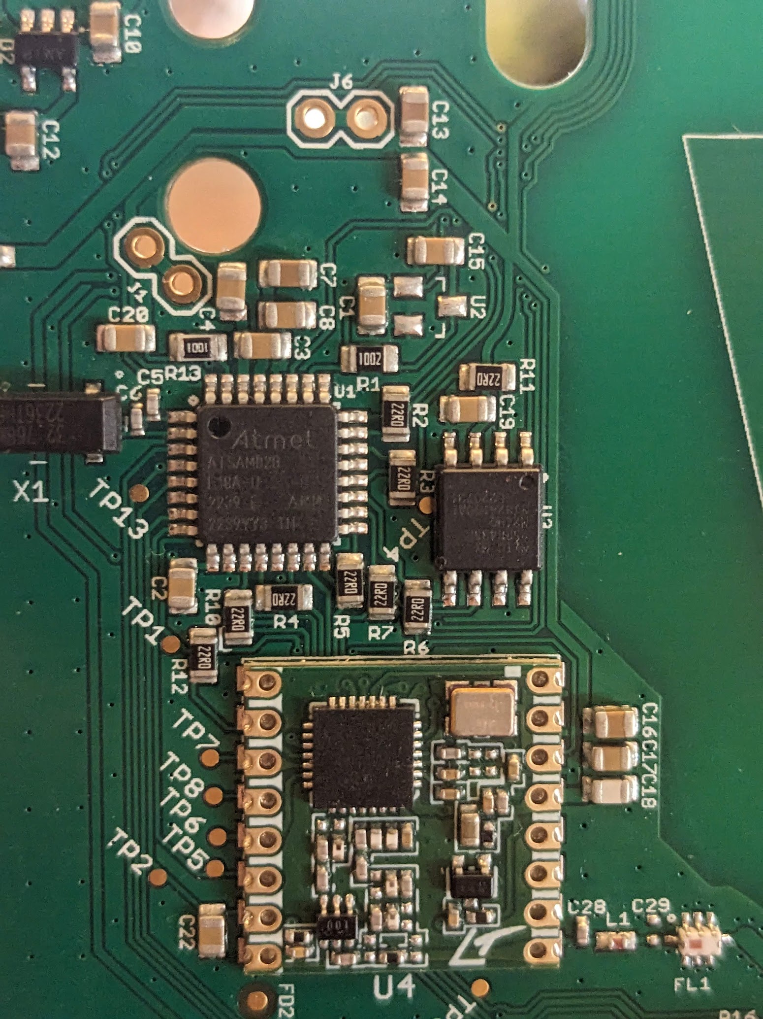
We can also see that the antenna is connected to an RFM69 packet radio module and that’s clearly the module used to transmit sensor information to the bridge. A ATSAMD20 microcontroller is also on the board and surely handles all the job of collecting data from the sensor, storing it in some kind of buffer and sending it off to the bridge through the radio module. We can probably speculate that because this device must be designed to last as long as it can on limited battery power, and because most homes are not continuously using water, this ATSAMD20 must enter its very low power standby mode, living there most of the time and wake up when the magnetometer senses water flowing and probably also periodically to deliver heartbeats and other information like battery state to the bridge.
The Bridge
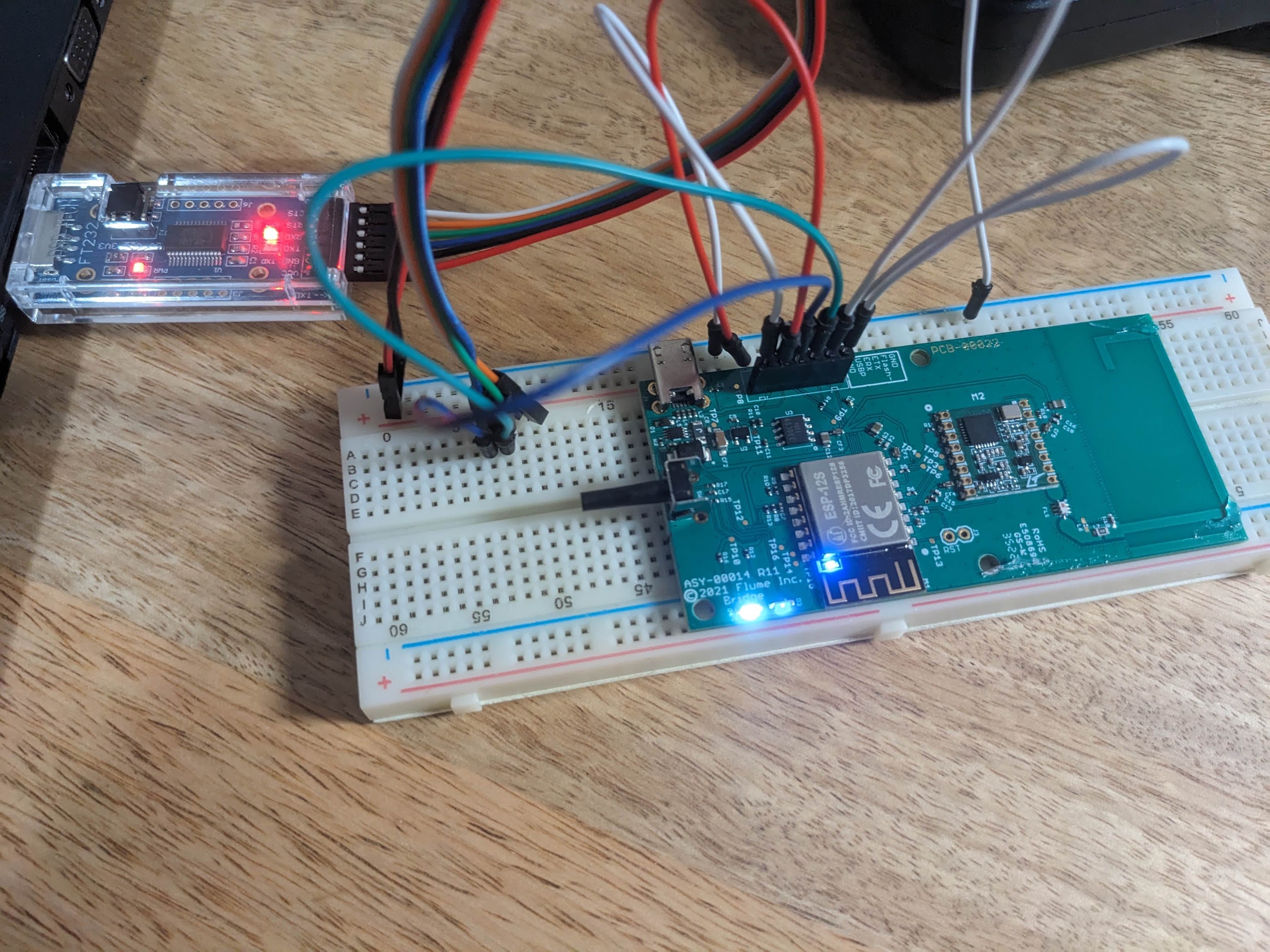
The bridge is a much smaller device and its designed to live inside your home. It takes power from the provided microUSB adapter. Looking at the board, its very easy to spot the major components. A 900Mhz antenna is compactly printed in a spiral shape at the top, and that antenna is connected to a corresponding RF69 packet radio module. And the whole thing is managed by an ESP-12S, an ESP8266 type microcontroller with embedded WiFi. Flume graciously labelled and printed pins that could be used for a uART connection to the microcontroller. So before we do anything else, let’s see if we can dump the flash image. Then after we run through the setup, we can see what changes and hopefully gain some insight into how it all works.
I placed some breakout pins right onto the board, tied the flash pin low and connected my trusty CH340. Powering on the bridge with the serial connection yielded a bunch of gibberish output. I tried all the usual baud rates none of them seemed right. But esptool, after a few minutes, was able to retrieve the flash image. We’ll get much deeper into this later, but for now, its plenty interesting to explore this with plain old strings. Lots of information is available just by looking at the text from the firmware image. Text that I found indicate about what would be expected. I see evidence of machinery for doing OTA updates, some kind of buffer, possibly for storing water use data, CRC checks, DNS, JSON encoding, packet radio interface stuff, library names and even some interesting hostnames. One that really stood out is mqtt.prod.flumetech.com.
Data Access Attempt 1
With a little luck, I figured I could set up my own MQTT server and grab the data I want. So I began by simply configuring my home router’s DNS service to resolve mqtt.prod.flumetech.com to my laptop’s IP address. Firing up Wireshark and powering on the bridge confirmed my suspicion that the bridge makes a plain, non-TLS network connection to a remote MQTT server. Monitoring the network traffic even revealed the username and password that can be used to connect. This was going to be easy. Or so I thought.
I used a few node.js libraries to cobble together my own custom MQTT server to accept connections from the bridge and relay packets to and from Flume’s own cloud service. This allowed me to sit in the middle and read all the packet data flowing in both directions while everything continued to work perectly fine.
Bridge subscribing, subscribing to Flume: responses/61DA80B5********/# 61F6F579********
Bridge to Flume: 2/7/12/61F6F579********/1733118561 134B ��Ӹ�|��Mk&8R��5B��\����)@�Z��.�p!�,c�ަ���f�C��*��}�
�
Pp*�JcZ a��
�!+,�K���ad�lo������$�'��*�Y���%��Jl
Bridge to Flume: 2/4/12/61F6F579********/1733118561 114B �ɧ����@Y9ν�78Wo�[�o�
�]�B�Uﺏ7y�Ԟ!�E�R#2�b�[�k^�~Q>eAӌ����������U0Q���ld��_�r�{-r�'U��6?��vAI@����
Bridge to Flume: 2/7/12/61F6F579********/1733118563 134B g��b
R��Ms�@#�Q0VR���p�g�}�2�A�&37A�[� �G���3hJg3v�`�Q�
\��8x[e>�=j����oe� Ł�����AYfF��O3��u��]�1E�p7M�C
GH��C�Y&����
Bridge to Flume: 2/7/12/61DA80B5********/1733118563 122B 1:A�Uҧ.����4m о�2/ƛz(�؏Z�>�����k��W c}R�q}��e�M�y#x�`�tWTS�_�Q)PW�`w�X�i
But there was a big problem. Although everything worked fine, I was not actually able to make any sense of the data I was seeing. Initially, I hoped it would be merely compressed. I recorded a good number of these packets and used some entropy analysis tools to confirm that these recorded data were very high in entropy. It probably wouldn’t make much sense to go through all the effort of scrambling all this data in a way that didn’t involve encryption, so I understood this to mean our data is encrypted. That’s going to make this a difficult road.
Data Access Attempt 2
Since data appears to be hopelessly encrypted once it hits the network, perhaps I’d have more luck intercepting it between the sensor and the bridge. To this end, I bought a few packet radio modules and microcontrollers and set off on this journey with an embarrassingly high confidence to skill ratio. I cobbled together a few programs to configure the radio as a receiver with parameters that seemed typical for this kind of communication, hoping that I’d be able to guess my way to successful data reception.
But as I learned more, I began to appreciate how complex and capable these little radio modules are. I read the data sheet multiple times until coming to the conclusion that the only path to success along this route was to determine with certainty exactly how the radio module needed to be configured. It was time to get a bit more invasive.
Data Access Attempt 3
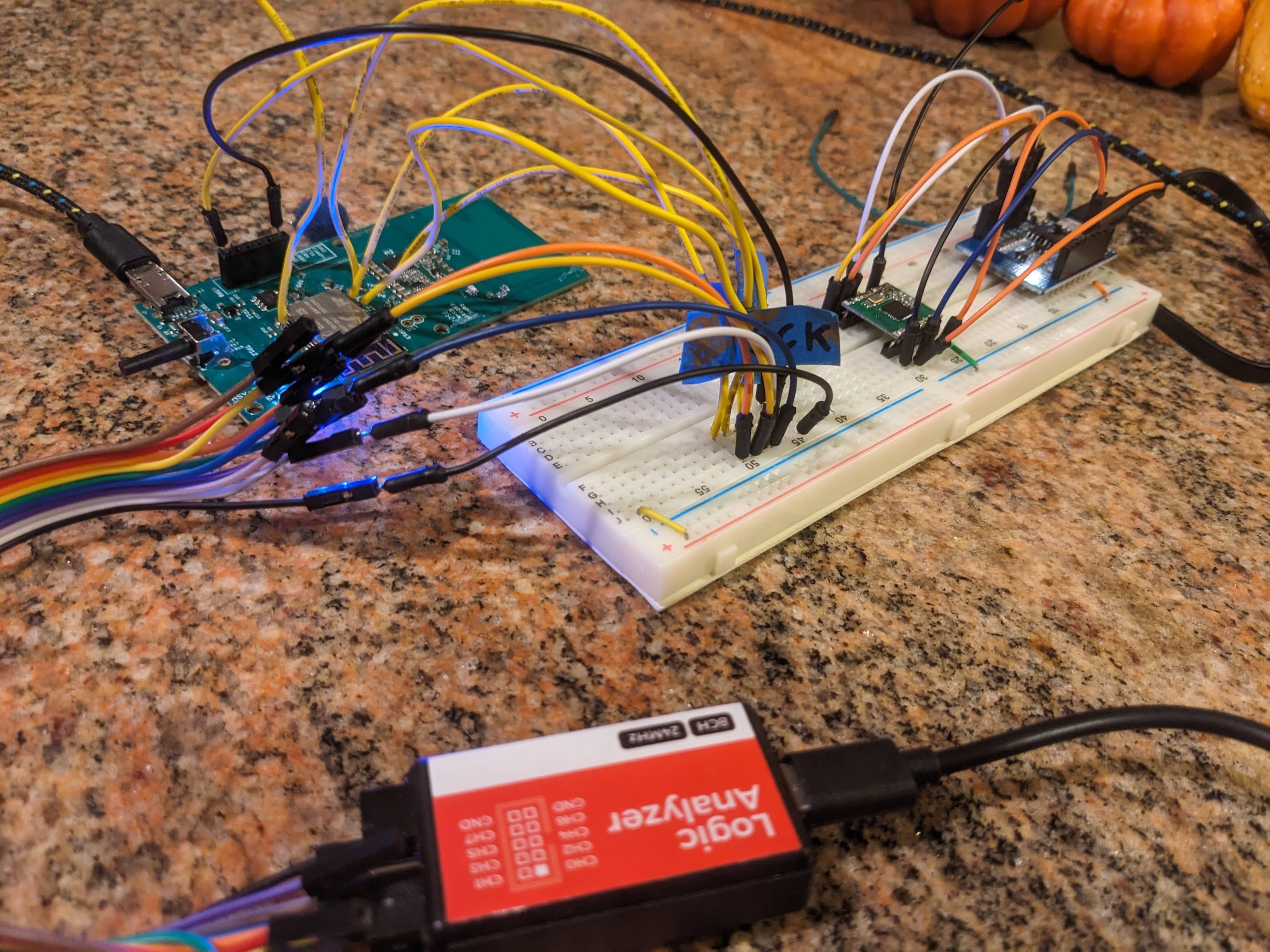
In order to learn exactly how the bridge configures its radio, I decided to observe the SPI bus between the ESP8266 and the RF69 radio module. Never having done this kind of thing before, it took many attempts before I had the right physical connections in place.
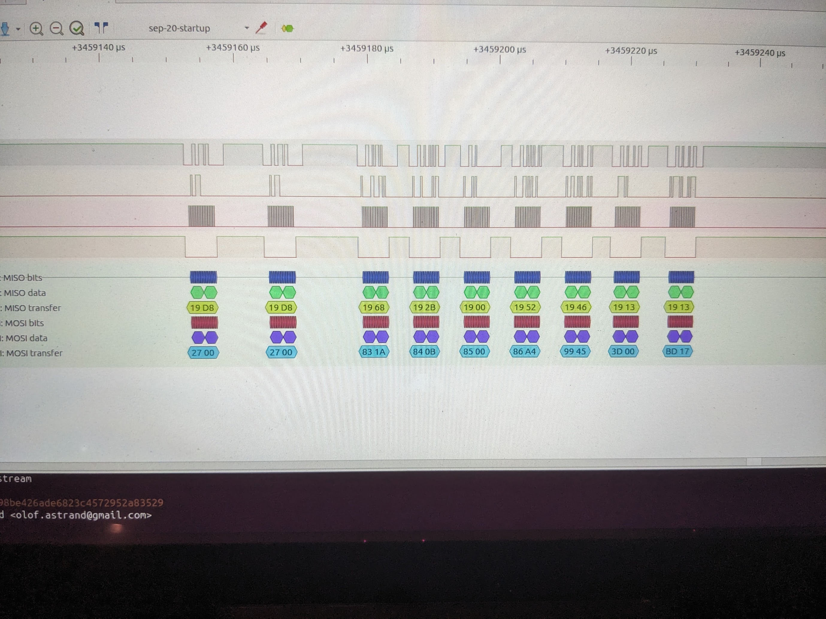
So I configured a separate microcontroller as a SPI slave device to observe the bus exactly as the radio module itself. I got some decent data, but ultimately got a much better picture of what was going on by buying a cheap 24Mhz fx2lafw compatible logic analyzer. PulseView served me quite well in capturing the samples and giving me a top-down look at what is on the bus.
The picture that emerged was far more complex than I had imagined. The packet radio was being very thoughtfully configured, and operating in a surprisingly fast frequency hopping paradigm, making its way through all 50 channels in a little over six seconds. Using 50 channels makes a lot of sense because FCC rules allow ISM band devices to output at higher power if they use at least 50 channels.
The data I had captured gave me everything I needed to know in order to reproduce the exact configuration and operation of this radio module exactly as the real commercial device was doing it. Not only did I have the radio configuration and encryption keys for the radio hardware, but also timing on how long to dwell on each channel, and fine tunings of bitrates to use, etc. Armed with the RF69 data sheet and complete disregard for the value of my own time, I dutifully transcribed the radio startup configuration sequence and operational configuration from SPI bytes into English so I could understand it, and then into code so I could implement my own bridge. I’m sad to say, I did this for days, but never picked up a single packet on my own.
I do believe this is potentially still a workable method, especially if the goal was to replace the bridge entirely. But as I was working on the approach, I realized there were some potential downsides even if I could get it working. The authentic Flume bridge was not merely receiving data from the sensor, but also seemed to be sending acknowledgments. And I began to wonder if having two bridges would potentially cause me to lose data in the event that the authentic Flume bridge were to receive and acknowledge data before my bootleg bridge. This worry made me reconsider my approach entirely.
A sensible person, if they had made it this far would simply be satisfied to catch this unencrypted data from the SPI bus. A simple microcontroller configured as a SPI slave could easily read all the unencrypted data from the bus and do anything. But this is such an inelegant hack. It requires physically modifying the lovely commercial Flume bridge and adding yet another microcontroller.
Getting the ELF
This is the point I am forced to admit that my initial goals are no longer relevant. I have direct access to the data I set out to access on SPI bus. Now this project has become an interesting puzzle and a fun learning opportunity.
I spent a few night attempting in vain to decrypt some packets I had captured previously using common encryption algorithms. I had hoped that trying some typical encryption algorithms along with the same keys that were used for packet radio communication, I could get that plain text with my man-in-the-middle MQTT relay. But it was not to be. I was going to have to dive into the software.
The flash image is pretty hard to work with as a unit. It does have some interesting strings and a lot can be gained by examining at this level, but you have to get quite a bit smarter about it if you want to learn more than the strings can tell you.
I dumped a new firmware from the bridge and flashed it onto a Wemos D1 Mini. It actually managed to start up and connect to my test MQTT server. This gave me a nice test platform so I don’t have to be messing with the authentic Flume bridge. Using my logic analyzer, I was able to determine the actual baud rate of the uART which is a very odd 50,000 baud. That allowed me to read some info from the startup sequence
rBoot v1.4.2
Flash Size:   32 Mbit
Flash Mode: QIO
Flash Speed:  80 MHz
rBoot Option: Config chksum
rBoot Option: Big flash
rBoot Option: irom chksum


Booting rom 0.
fs=32m-512
�����������������������������������������������������
nul mode, fpm auto sleep set:disalbe
mode : sta(b4:8a:0a:c6:7a:0e)
add if0
scandone
state: 0 -> 2 (b0)
state: 2 -> 3 (0)
state: 3 -> 5 (10)
add 0
aid 4
cnt

connected with crozz, channel 6
dhcp client start...
ip:10.10.6.66,mask:255.255.255.0,gw:10.10.6.1
pm open,type:0 0
Clearly, this image contains one or more ROMs, and a bootloader named rBoot. One of those ROMs should be the bridge software that runs during normal operation. It should have an entrypoint and it should begin its execution there. I spent a good deal of time learning how the official toolchain builds these flash images and how to reverse it. Esp-bin2elf is designed for this purpose, but I was not able ot get it running. I asked for some help from Richard Burton, the creator of this bootloader and he very kindly found a bug in esp-bin2elf, sent me a patch and then later created his own 2elf project which works great. I’m very grateful and I might not have made it any further without his help.
So now I have an ELF file which contains the actual user program extracted from the flash dump. The ELF file was surely created using the Espressif toolchain, with an unknown set of compiler flags and definitely no symbols. Thankfully the symbols that came from the toolchain’s own linker script are known and provided by esp2elf. That gives us at least a few symbols to work with.
Decompiling the Software
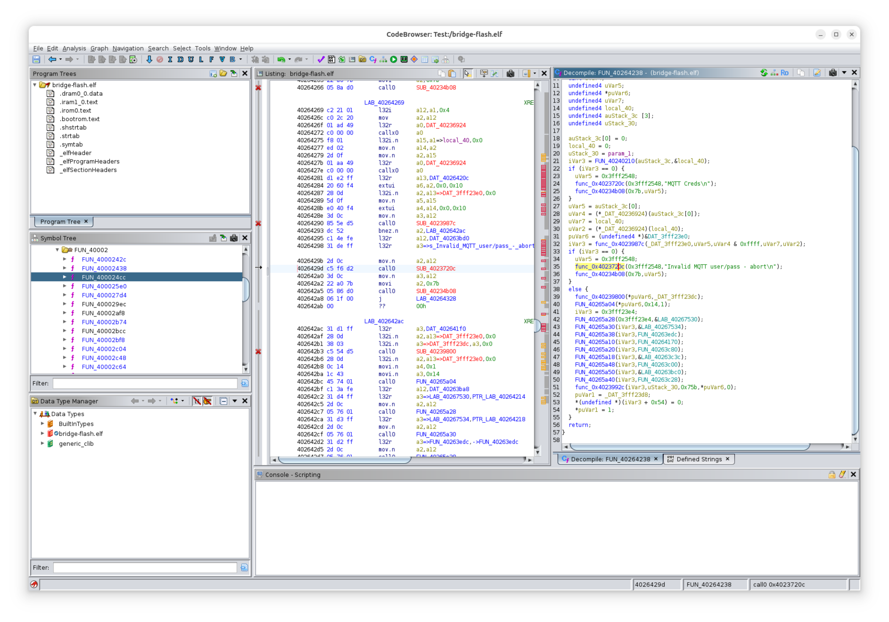
Ghidra is a reverse engineering tool published by the NSA. It actually supports the Xtensa CPU architecture used by the bridge’s microcontroller and should be able to decompile all this machine code into something more structured. And indeed it does. It is certainly a long way from having the original source code, but with quite a bit more patience, you can start to put together a picture of how it works.
Labelling a symbol table for a program compiled with all the usual compiler optimizations is a real chore. But it doesn’t have to be complete or even 100% correct in order to be useful. You can jump around, making guesses, then correcting those guesses until it starts to fill in. I found it easiest to start from error messages and work from there. Its pretty common to see a call to a subroutine and then a check on its return parameter, and finally a message like “X failed.” That’s a pretty clear sign that the called subroutine was for X.
Some functions are quite difficult to parse, and I learned through this process that this program isn’t just a user program, but actually a whole operating system based on FreeRTOS running a program which makes it that much more difficult to follow.
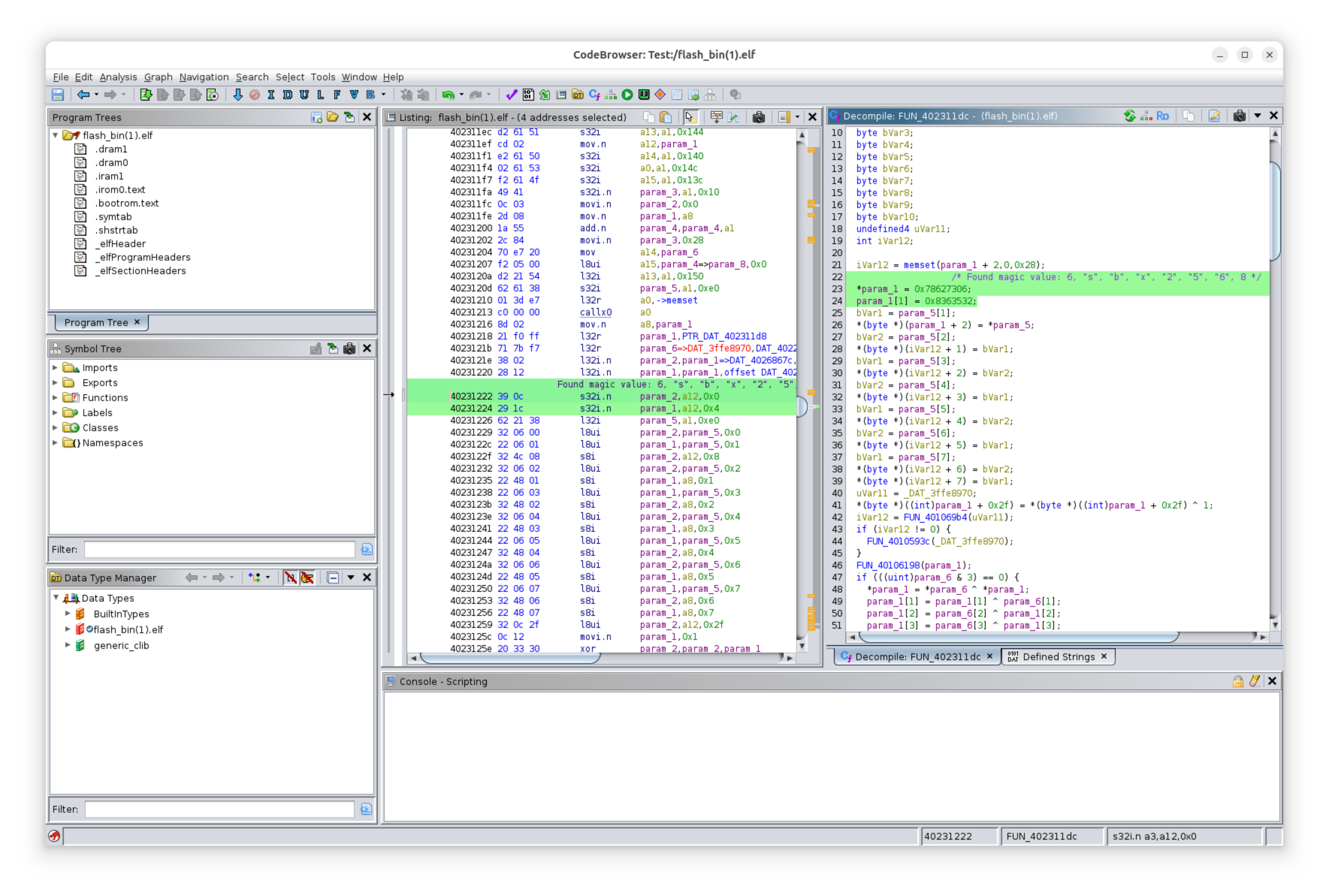
I was searching through thousands of unlabelled, decomiled C functions, looking for something that resembled encryption so I could further understand what was happening on the network. I actually found LLMs to be somewhat helpful here. In one function, the LLM called out an interest in a particular value at the end of a long summary:
In essence, this function applies a series of bitwise operations and conditional logic to an input array of uints. It appears to be performing some kind of transformation on the array, possibly related to encryption or hashing (based on the use of shifts, XORs, and a constant like 0x9e377900, which is commonly associated with hash functions like MurmurHash).
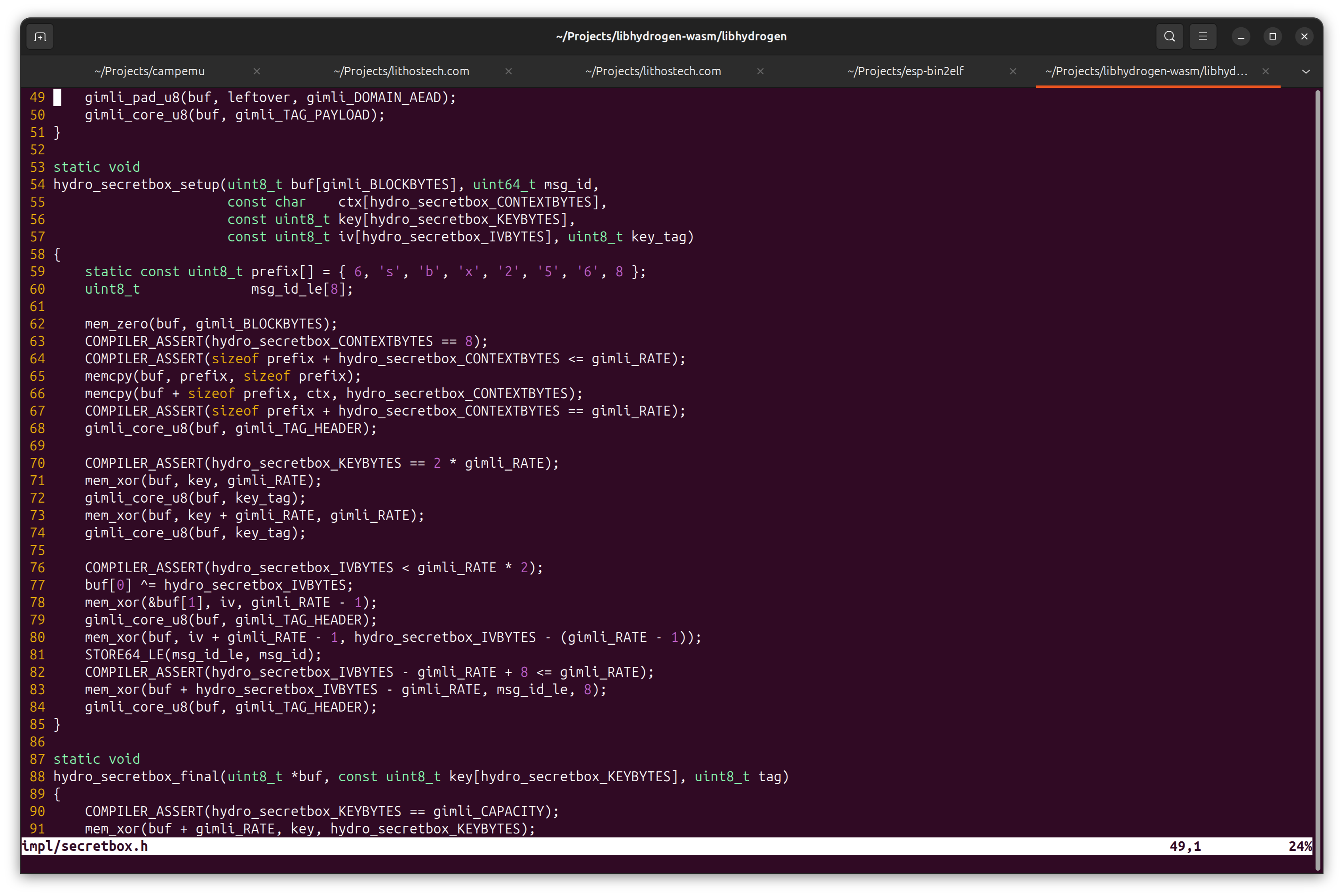
The LLM had some other guesses as to which encryption algorithm this might be. They were all wrong, but it was correct to be interested in this value. It was paying attention to the right thing. It turns out this value is approximately the fractional part of the golden ratio, and this particular approximation is used in the Gimli permutation. The Gimli permutation is used in LibHydrogen, a somewhat popular cryptography library. Its lightweight properties make it a pretty good match for the capabilities of the hardware and demands of this application. Further analysis of constants defined in LibHydrogen and the decompiled bridge software confirm this is indeed the library used for encrypting and decrypting MQTT packets.
At this point, I have a practical MQTT relay that can handle and observe traffic to and from the bridge device. I also know exactly which kind of encryption is in use down to the library and even the functions from that library that are in use. But I still can’t read the data on the wire because I don’t have the keys or the expertise to understand the encryption scheme.
The second part is easily addressed. I was going to need this anyway, so I set about creating LibHydrogen bindings for JavaScript using Emscripten. The process of creating these bindings and writing the tests taught me a lot about how to use LibHydrogen and gave me some confidence to press on.
The scheme used by the bridge for encryption is surprisingly robust. When I began this project, I imagined I’d be up against something far less secure. But the engineers at Flume used modern tools to design something with pretty good security. A key pair must exist at Flume, and another key pair exists on the bridge. Code exists on the bridge for deriving subkeys from a master key, so that bit of complexity may be at play. There is also likely a key exchange step for deriving session keys which can then be used to exchange messages.
I had found a routine in the bridge software that appears to request, receive and store a new public key from Flume. If I was able to trigger this routine, I could conceivably generate my own key pair using LibHydrogen and send it to my bridge. If I could manage this, I could play with one side of my MQTT relay without bothering Flume. The trouble is, I have no idea how to reach this code. It seems to be triggered potentially after an OTA update or in response to a specific command. But as all the traffic I’ve observed so far has been encrypted, I have very little idea how these commands should be sent. There is clearly a whole mini-protocol built into this scheme.
Altering the Image
The code I found that loads the public key from flash memory address 0x3f9000 into RAM checks to make sure it begins with a magic prefix. I wondered if I were to alter this image, if I could get the device to request a new public key and see what that communication looks like. So I changed the magic value and loaded the firmware onto my own ESP8266. The device connected to my MQTT server and did not request a new public key. But it did in fact begin sending messages in plain text! I made the same change and uploaded this altered firmware to the real Flume bridge half expecting to see all the plain text flowing. I got a look at some interesting unencrypted messages coming back from Flume, including one message identifying the server’s libhydrogen bindings which are from Phydro.
Bridge Connected: 61F6F579********
Bridge subscribing, subscribing to Flume: responses/61F6F579********/# 61F6F579********
Bridge subscribing, subscribing to Flume: responses/61DA80B5********/# 61F6F579********
Bridge to Flume: 2/7/2/61F6F579********/1733208825 98B {"bridge_id":null,"branch":"lrange-release","sha_full":"e8c2db4b80c39c39c41a1d28318feeb81ac035d8"}
Flume acknowledged bridge subscription
Flume acknowledged bridge subscription
Flume to bridge: responses/61F6F579********/1/2: 321B {"code":602,"message":"Request OK","timestamp":1733208825,"sensors":["61DA80B5********"],"devices":[{"uuid":"61DA80B5********","hardware_id":"ASY-00007"}],"settings":{"1":1,"2":"/provisioning","3":"/frames","4":"/responses","5":"device.flumetech.com","6":30000,"7":1200000,"8":4093,"9":65281,"10":14,"11":261135,"12":12}}
Bridge to Flume: 2/9/1/61F6F579********/1733208826 32B ��B��|G���n ��� 4O@c�� ��?7g
Bridge to Flume: 2/3/2/61F6F579********/1733208826 285B [{"timestamp":1733208826,"type":1,"level":4,"message":"RST REASON: DIRTY "},{"timestamp":1733208826,"type":1,"level":4,"message":"SDK reset #6: external"},{"timestamp":1733208826,"type":1,"level":4,"message":"SHA: e8c2db4b80c39c39c41a1d28318feeb81ac035d8 | BRANCH: lrange-release"}]
Flume to bridge: responses/61F6F579********/6/2: 90B {"code":174,"message":"Phydro crypto key exchange function failed","timestamp":1733208827}
Bridge to Flume: 2/4/2/61F6F579********/1733208829 111B [{"timestamp":1733208829,"type":1},{"timestamp":1733208829,"type":1024},{"timestamp":1733208825,"type":16384}]
Bridge to Flume: 2/3/2/61F6F579********/1733208831 82B [{"timestamp":1733208827,"type":1,"level":8,"message":"Server error [code 174]"}]
Bridge to Flume: 2/7/2/61DA80B5********/1733208836 86B {"bridge_id":"61F6F579********","sha_full":"163be969f421472b2fb0d890a8be0ae45e4773a5"}
Flume to bridge: responses/61DA80B5********/1/2: 239B {"code":602,"message":"Request OK","timestamp":1733208836,"last_sample_timestamp":1733111130,"sensors":[],"peaks":2905840,"settings":{"1":16383,"2":2097151,"3":60000,"4":14,"5":511,"6":5,"7":30,"8":600,"9":0,"10":0,"11":2,"12":150,"13":0}}
Bridge to Flume: 2/2/2/61F6F579********/1733208844 73B [{"timestamp":1733208844,"4":27824,"16":20,"512":-65,"1024":6,"2048":1}]
Bridge to Flume: 2/9/1/61F6F579********/1733208862 32B ��9�-,��-ȰT�m��
Flume to bridge: responses/61F6F579********/6/2: 90B {"code":174,"message":"Phydro crypto key exchange function failed","timestamp":1733208863}
Bridge to Flume: 2/3/2/61F6F579********/1733208865 82B [{"timestamp":1733208863,"type":1,"level":8,"message":"Server error [code 174]"}]
I like this software direction as it could be possible to access my water use data without additional hardware, and aside from a few headers tor firmware flashing, doesn’t require any nasty bus sniffing hardware modifications. This approach also benefits from the fact that the bridge does some useful stuff. Beyond relaying raw sensor data, its also storing up a buffer, keeping track of state, and the MQTT layer at the top of the stack is simply a more friendly layer for observing data. Of course, a remote firmware update could easily defeat my plan.
But something was quite wrong. Perhaps this was never going to work, or perhaps my messing around caused some state to be reset at Flume. Either way, I disconnected my experiment and reflashed the original firmware to the bridge, tried to setup from scratch. This did not get me reconnected and I ended up on a support chat and getting a replacement sensor which is interesting because I hadn’t been messing with the sensor. So I’ve probably caused enough trouble as it is and at some point, I do need to call it quits.
I’ve been in this for the puzzle solving, but I have to stop myself from spending more time on this before it consumes me. The SPI bus is always there if I really need it.
What’s Next
There’s precious little to show for all the effort spent on this project. But I learned a lot and had some fun working on my first serious attempt to reverse engineer some hardware. I wanted to make all this research available in case anyone else is interested in taking this further. I hope my research will get you a much faster start than I had.
It looks as though the encryption scheme is asymmetric and strong. Without Flume’s private key there may be zero chance of reading this data as it stands. But it should still be possible to generate a new key pair and get the bridge to accept that public key. In this way, I imagine a MITM like my Relay program could receive and decrypt the bridge data, and then re-encrypt it on the way back up to Flume using their public key, and vice versa.
There is so much more to understand about the bridge software. There are clearly debug modes available on the Bridge. It seems like it should be possible to get the program to enter into one of these modes with some more cleverness, and if it is possible, the program should emit a bunch of useful messages which would help in monitoring program state, at least in the areas that have been instrumented with debug logs.
Alternatively, it should be possible execute this software and step through the instructions. The interesting routines and memory addresses are all knowable and single-stepping would make it a lot easier to understand the tricky parts.
I did attempt this with a JTAG interface, but I have no experience with this and have had no luck yet either using JTAG to debug or with running the program directly in Qemu+GDB.
I could use more of my time to try to run this program with my eyeballs and brain to suss out the remaining bits that I need. This is what I’ve been doing so far, but it is slow and very hard! The decompiled code includes a lot of labels and jumps and dynamic function calls making it pretty difficult to follow. The trickiest part has been trying to keep track of program state and what exactly is stored in memory. But maybe a bit more dedication could get me the rest of the way.
I’ve also considered attempting to recompile the decompiled code so I could add GDB stubs and debug remotely via uART. But that’s looking hard too, and even if I did fix the thousands of compilation errors, I don’t think there’s any guarantee it would run correctly. So far that has discouraged me from pouring much energy into attempting to compile the whole program. Perhaps in a more practical variation on this approach, I could compile only specific functions so I can observe them in action.
Building a plain radio receiver around the RF69 also seems like a nice, noninvasive way to capture the data on its way from the sensor to the bridge. This should be very doable.
If there are any other Flume device owners out there with the time and energy to take this investigation even further, I’d love to hear about it.
To the Folks at Flume
At some point, someone at Flume will likely catch wind of what I’ve done. Maybe they already have. Through this process, I’ve developed a much deeper respect for this problem domain and some of the details that go into building this kind of consumer hardware product. It’s worth pointing out that what I’ve done has surely voided whatever warranty came with my hardware, and I don’t recommend doing any of this unless you’re prepared to ruin your hardware and potentially even your relationship with Flume. I hope we’re all still on good terms and have hopefully even had a good laugh at my wild investigation.
If you’re still reading, I’d like to request a feature! I’d like my bridge to post data in plain text to my own local MQTT server or some other Home Assistant based on local control. I’m glad I get access to my data at all through the Flume API, but access is not the same as ownership or control, and I do believe that when I buy a water use monitor like this, I should both own and control my own water use data.
If you ever want to meet, I am just down the road in Santa Barbara. But even if not, you’ve got my respect for creating this excellent product and paying such careful attention to security.
