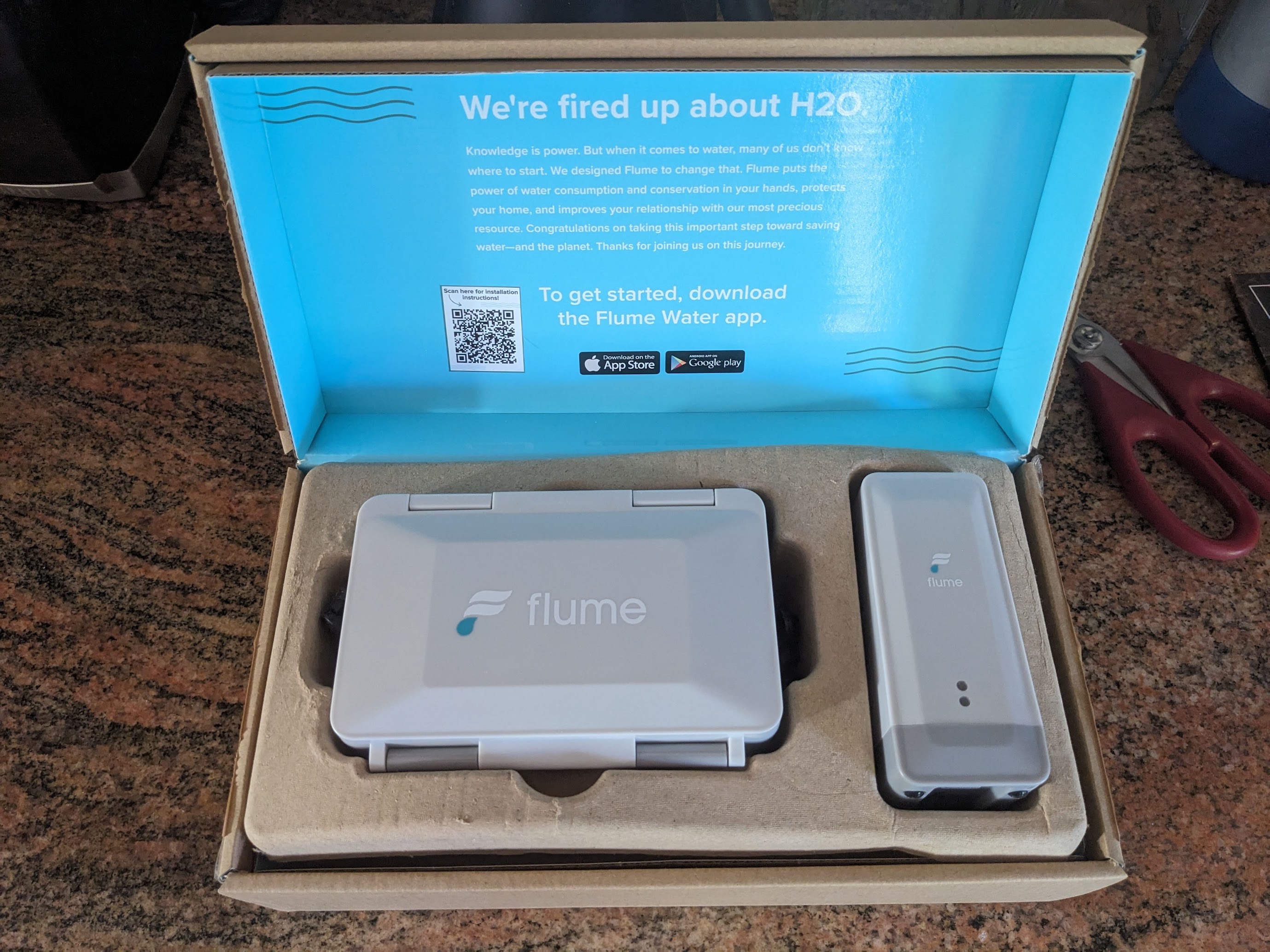
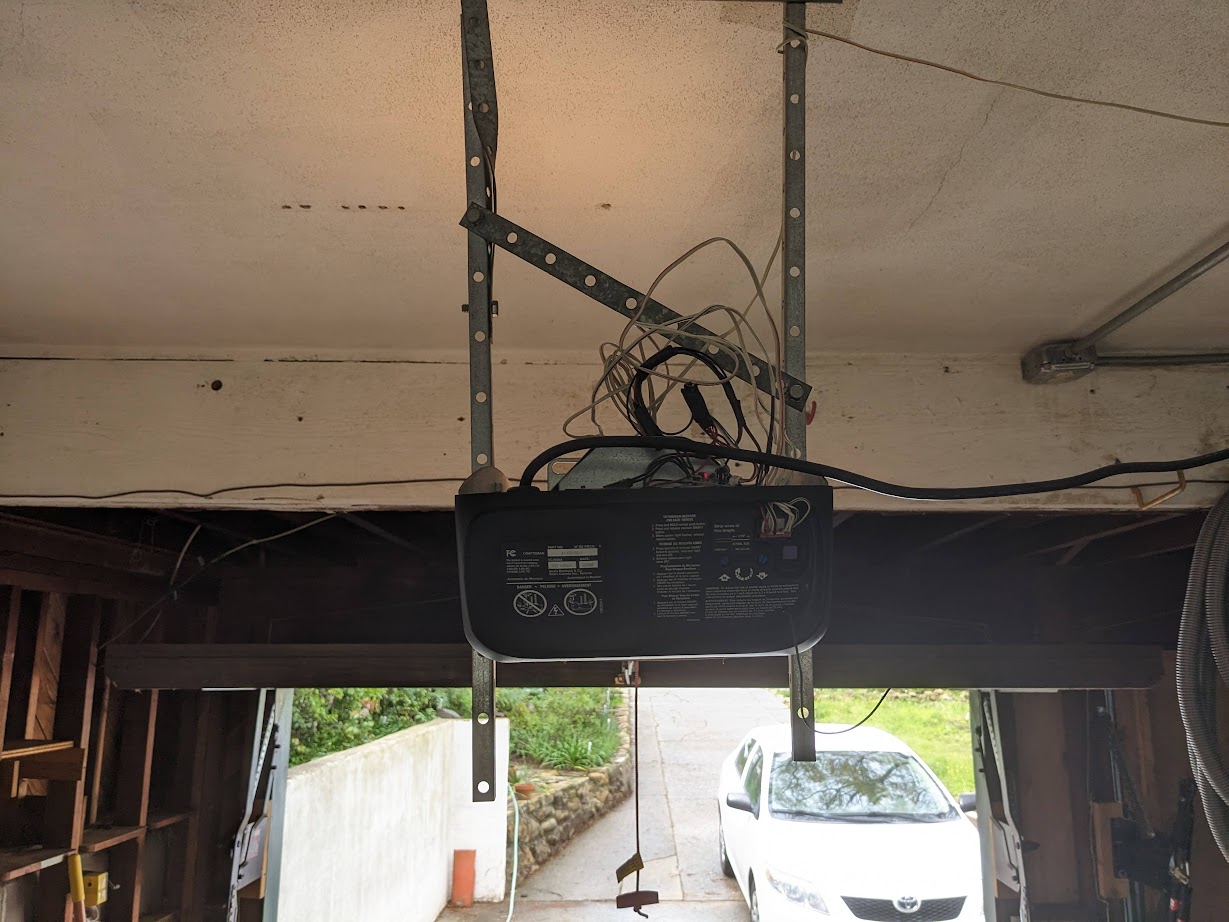
In 2023, I managed to integrate my garage doors with HomeAssistant using a Shelly Uni device. Controlled remote operation is pretty great, but I wanted to document this project because this solution covers remote door control, door state and even door light control is possible, using a single $12 device with no batteries required. The setup is easy to achieve, and leaves all the garage door opener functionality in tact.

Garage door opener, with Shelly Uni attached

Overview

  • Shelly Uni device is powered from a 12v DC power source leeched from the low-voltage side of the garage door control circuit board
  • Garage door switch is operated using one of the two potential free outputs on the Shelly Uni
  • Garage door state is monitored using both Shelly Uni inputs, detecting open/closed circuits on the garage door opener’s own state sensors
  • Light control is not implemented, but could be added to the extra Shelly Uni output in an extremely simple circuit

Shelly Uni

I found the Shelly Uni after having played with a few other devices in the Shelly ecosystem. These devices are excellent. They are easy to set up via captive WiFi portal. They of course join your WiFi network. They can be controlled locally with no cloud services via their own built-in web servers, HomeAssistant, or other local message systems. I have nothing but good things to say about my experience with these devices.

Shelly Uni, opening

The Uni in particular is well suited for garage door control and state monitoring because of its flexible power input specifications (AC 12V – 24V or DC 12V – 36V), because it can be configured as a momentary switch just like the physical garage door wall-mount button, and has those two inputs which are perfect for observing state which I will get into later.

Getting the Cover Off

Garage door opener unit, still mounted on the ceiling with the case off

One of the trickiest parts of this garage door opener modification was getting the case off. I’m not garage door service pro, so figuring out how to get this case removed was a slow process. Maybe this is easier if you remove the whole unit from the ceiling, but I didn’t want to do that. In the end, I did manage to get the cover off the unit without breaking anything and without the use of a grinder.

With the cover off and the unit safely unplugged, I was able to get a good look at the internals. The bulk of it is obviously the large drive motor, but there are also two circuit boards in the back. You can see the mains voltage connected directly to the smaller brown board, and power leads for the motor and lights leading out.

Power Source

Garage door opener circuit boards, facing the mains voltage side

My first order of business was to get these circuit boards off the ceiling and onto the bench for a closer inspection. My plan was to find a suitable power source somewhere on one of these boards, and assume that the load of the tiny Shelly Uni wouldn’t even be noticed. One very easy source appeared to be the step-down transformer which was clearly labeled 22VAC, well within the documented input range of the Shelly Uni. But when I measured the actual potential it was out of range at 28VAC. But on the low voltage side, I found a nice 12VDC right on the connection between the two boards.

Power leads wrapped around connector posts on a circuit board

I did not feel like soldering directly to the circuit board, so I wrapped the posts of the connector with some solid copper wire before plugging the boards back together and re-assembling.

Door State

The garage door opener unit itself needs to be able to detect when the door is fully opened or fully closed so it can stop the motor. To do this, my unit has a very simple, ingenious, and adjustable mechanism. Through a series of nylon gears, the movement of the door causes a grounded carriage (connected to the gray wire) at the front of the machine to traverse the space between two separate +5V (yellow and brown wire) contacts.

Garage door state detection switch

Garage door opener unit case with hole drilled on top

So the potential measured between the yellow and gray wires is 0 when the door is fully open and +5V when not fully open. The potential between the brown and gray wires is 0 when the door is fully closed and +5V when the door not fully closed. So with these three contacts, and the two inputs on the Shelly Uni, we can know when the door is fully open, when it is fully closed and when it is neither.

Garage door opener unit case with hole drilled on top, now with a rubber grommet installed

All that was left was to wire it up and find a place for the Shelly Uni to live. I wasn’t sure about packing it all into the metal garage door casing. In hindsight, I probably could have managed it and it would have looked nicer. But I wound up drilling a hole in the case and routing the cables through a rubber grommet on top.

It has been over a year now and this setup has been working great on both my garage door openers. I have it integrated with HomeAssistant which makes for very convenient remote operation. At one point, wall-mounted button was sticking and I believe the stuck button somehow triggered a factory reset of the Shelly device. But I did clean that plastic switch and lubricated it with mineral oil and it hasn’t had a problem since.

HomeAssistant Configuration

You don’t need to use HomeAssistant to make use of this setup, but it is quite nice. In HomeAssistant, garage doors can use the ‘cover’ template and my configuration looks like this:

cover:
  - platform: template
    covers:
      garage_door_right:
        device_class: garage
        friendly_name: "Garage Door - Right"
        unique_id: garage_door_right
        position_template: >-
          {% if (is_state('binary_sensor.garage_door_right_channel_1_input','on') and is_state('binary_sensor.garage_door_right_channel_2_input','on')) %}
            {{50|int}}
          {% elif is_state('binary_sensor.garage_door_right_channel_1_input','on') %}
            {{0|int}}
          {% elif is_state('binary_sensor.garage_door_right_channel_2_input','on') %}
            {{100|int}}
          {% endif %}
        open_cover:
          service: switch.turn_on
          data:
            entity_id: switch.garage_door_right_channel_2
        close_cover:
          service: switch.turn_on
          data:
            entity_id: switch.garage_door_right_channel_2

Continue reading »

The Byte Clock prototype, assembled and powered on 
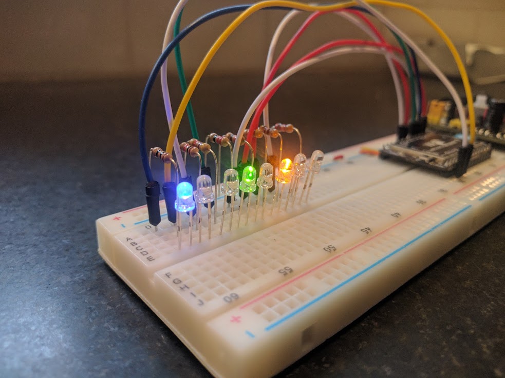
A binary clock is hardly a new idea, but this particular concept is something I haven’t seen anywhere else. And it was idling in the back of my mind for over a decade before finally seeing a working prototype.

Concept

The passage of time can be measured in any number of ways, but when a clock is designed for humans, I think it should be based on a natural concept. Since I live on Earth, I designed a clock, as many others have, based on the smallest natural temporal concept I can readily observe: the day.

The day is plenty useful for medium-term planning, but it lacks the precision needed for many purposes, and so it must be divided in order to build a useful clock. This is where clock design becomes much more arbitrary. Dividing the day into 24 was supposedly based on astronomical observations of various stars passing in the night, but beyond that, there’s no natural reason there should be 60 minutes in an hour and so on.

My thought, is that the simplest and most natural way to divide a day would be in half. This is essentially the AM/PM indicator which is a concept so natural and necessary, that even many of our 12 hour clocks use it to avoid the otherwise ambiguous information displayed. But if the most natural way to divide a day is in two, then maybe the next most natural division is in two again. Dividing a day repeatedly in two results in a kind of binary clock. And this is exactly the concept.

Design

Let’s explore the design I’ve had in mind. This idea has taken many shapes in my head over the years, but the picture I’ve had in mind most often is a series of LEDs, each representing a successive division of one full day.

For a practical, human-oriented clock, we’ll need enough precision to be useful for normal human activity. One single LED cuts the day in half, providing half-day precision, but that’s far too granular to be able to plan intra-day activities. Adding two more LEDs takes the precision down to 1/8th, and with four you get 1/16th of a day. For any number of LEDs, the precision of this clock is 1 / (2 ^ n).

Since this way of dividing days is unfamiliar, let’s look at further divisions to see what it would take to end up with a useful clock. Each item below shows the level of precision (in 24 hour terms, rounded to the nearest second) that could be reached with the given number of LEDs:

  1. 12:00:00
  2. 06:00:00
  3. 03:00:00
  4. 01:30:00
  5. 00:45:00
  6. 00:22:30
  7. 00:11:15
  8. 00:05:38
  9. 00:02:49
  10. 00:01:24
  11. 00:00:42
  12. 00:00:21
  13. 00:00:11
  14. 00:00:05
  15. 00:00:03
  16. 00:00:01

In order to approach one second precision, we would need 16 individual LEDs. And even that final light would represent a period of time slightly longer than a second. But down-to-the-second precision isn’t often required in day to day human activity. Since I want to learn to read my own clock, I decided to try to keep the display as simple as possible, and that means using as few lights as I can get away with.

Eight LEDs give me a good balance. I don’t usually need more precision than I can get out of eight bits and keeping the LED count down to eight should make the clock easier to read. Here are a few examples of how this clock display could be translated into conventional 12/24 hour format.

o o o o o o o o <-> 12:00:00am
o x o o o o o o <-> 06:00:00am
x o x o o o o o <-> 03:00:00pm
x o x x o o o o <-> 04:30:00pm
x x x o x x x o <-> 10:18:45pm

The first few digits are very easy to learn to read, but they get more difficult if you plan on translating them to the convetional format in your head. One of the things I’m most curious about, is how hard it will be to learn to understand the meaning of this clock without having to do the conversion.

The information in the clock gets progressively more granular as you read from left to right. It may be that the first 4 LEDs can give you all the precision you need, but as with a conventional digital clock, you can decide where to stop reading when you’ve gathered enough information.

Hardware

The recent explosion in the number of low-cost WiFi enabled development platforms was the driving force behind why I finally started on this project. Previous systems were either too bulky, power hungry and expensive, or would have required a lot more effort on my part.

In order to avoid implementing a system for manually setting the current time on this clock, I wanted a platform that included easy internet connectivity so the clock could set itself using NTP. For me, WiFi was part of this requirement along with all the nice network interface features we’ve come to know and love like DHCP support and a working TCP stack and preferably HTTPS support in case I want to get really fancy.

Of course, a real-time clock (RTC) is important when building a clock and it’s nice to have one built-in. It’s always possible to add your own, but my hardware experience is limited and a microcontroller that includes an RTC allows me to skip that hurdle. I also wanted enough I/O pins with enough power to drive 8 LEDs so as to not require fancy multiplexing or extra circuitry. Other concerns are power consumption, cost, and how easy the platform will be for a software person like me to learn.

In the past, for WiFi connected projects, I’ve used arduino and a repurposed wireless home router because those were the best options available at the time. But today, there are all kinds of other interesting options. WiPy is the one I ended up on for no particular reason other than I found it early on in my search and it ticks all my requirement boxes.

One other interesting thing about the WiPy is that you can write software for it using tiny version of Python called MicroPython. For me, this is an advantage over alternatives like Wiring/Processing which I’ve battled before. Python is a more comfortable environment.

Software

True to my open source roots, I created a GitHub project to house and track the evolution of the software that drives Byte Clock. I likely won’t do a whole post on how the software works because it will likely evolve and anyone with sufficient interest can keep an eye on the GitHub project for updates. It’s enough to say that the software is responsible for synchronizing the real time clock with an NTP server and managing the state of the clock’s display.

Blinking an LED

In addition to the WiPy microcontroller, I bought a cheap 3.3v power supply from Amazon and a bread board. The power supply takes 6.5-12v DC input and provides 3.3v or 5v DC output. In this photo, I’ve got the power supply and the WiPy connected on the bread board. Here’s what it looks like powered on for the first time.

WiPy Powered On

Getting up and running with the WiPy was pretty simple once I figured it out. When the WiPy powers on for the first time, it creates its own wireless network which anyone can join and from there you can upload your own code over FTP. Adafruit has a handy guide with more detail on how to get started.

Here’s a very exciting video of the moment when I made it past the first hurdle, blinking an LED.

WiPy with 1 IO pin hooked up to an LED

Setting Up the Display

The clock display amounts to a binary counter, so that was a natural next step. I chose eight different colored LEDs and hooked them up to the first eight I/O pins on the WiPy. The various colors have differing forward voltage Vf values and different brightness properties. In order to roughly match the brightness levels, I had to choose different current limiting resistor values for each one. Attempting to match the current of each LED methematically resulted in wildly differing brightness levels, so choosing the right resistor values ended up being a lot of trial and error.

The display test program didn’t take long to write. Here it is in action.

Implementing the Clock

With the LEDs connected to the WiPy and the WiPy connected to the internet, the rest is software.

It would have been awesome to build a Byte Clock without having to use a conventional clock to drive it, but that was the simplest available option. If you examine the source code, you’ll see the time keeping is done using the MicroPython RTC class. The system boots, grabs the current time from an NTP server, sets the real-time clock and sets a timer to increment the display state every interval.

The Byte Clock prototype, assembled and powered on

Next

I’ve had this clock running on my kitchen counter for a few months and it’s still keeping accurate time aside from missing the time change. I’ll need to implement that function. Thinking about this clock has made me ask all kinds of questions about the nature of conventional clocks and how we go about our days.

For instance, why should clocks start at midnight? And what exactly is midnight by the way? Would it make sense for clocks to start counting at sunrise or noon instead? It might, and I haven’t ruled out playing with that idea. But going down that road makes conversion to convetional 24 hour time a lot more difficult.

Why should clocks count up and not down? We could just as easily design a clock that counts down the time remaining in each day. Would that be good?

Communicating information about moments in time with the byte clock is presents a challenge. Reading all eight digits aloud would be inconvenient (“on off on on on off off on”). But since this is a Byte Clock, the time could be expressed with just two hexadecimal digits (b9). That’s a pretty concise way to express the time of day at this level of precision.

After pondering the differences between the Byte Clock and conventional clocks, it seems more clear that the values 24 and 60 are not at all arbitrary. Conventional clocks are easily divided in half, thirds, fourths, sixths and eigths. The Byte Clock is, of course, only divided easily by powers of two. I think I knew this all along, but having built this clock makes me appreciate this aspect of conventional clocks.

Next, I’m planning to play with the arrangement of the LEDs with the goal of making the clock easier to read. And after that, I’d like to design a slick looking case and build something that looks a bit more professional.

Continue reading »

Now that TLS is free, there’s very little excuse to be running web services over plain HTTP. The easiest way to add TLS to this blog was through AWS Certificate Manager and its native CloudFront Support. But for a while, there was a problem. In order to use a free, trusted certificate from Amazon, I needed to be using CloudFront. In order to be using CloudFront, I needed to be able to resolve the name ‘lithostech.com’ to a CloudFront distribution. Since DNS doesn’t support CNAME records on top level names, that meant switching DNS service to Route53 where Amazon has a special solution for this problem they call alias records.

But there was a problem because Route53 doesn’t have DDNS support and I use DDNS to reach my home network’s dynamic IP address when I’m out of the house. And so I put this off for quite a while, mostly because I didn’t realize how simple DDNS really was and how easily it could be done with AWS Lambda.

Turning to the source code for ddclient, a popular DDNS client that ships with Debian, I found that DDNS amounts to nothing more than calling a tiny web API to update a remote server with your current IP address at regular intervals. Each vendor that provides DDNS seems to implement it differently, and so it seems there is no specific way to do this. But in all the implementations I saw, the design was essentially a magic URL that anyone in the world can access and use it to update the IP address of a DNS A record.

A picture was beginning to form on how this could be done with very low cost on AWS:

  • API Gateway (web accessible endpoint)
  • Route53 (DNS host)
  • Lambda (process the web request and update DNS)
  • IAM Role (policy to allow the DNS changes)

On the client side, the only requirement is to be able to be able to access the web with an HTTP(S) client. In my case, a CURL command in an hourly cron job fit the bill. I enjoy the flexibility of being able to implement and consume this as a tiny web service, but it could be made simpler and more secure by having the client consume the AWS API to invoke the lambda function directly rather than through the API Gateway.

I put some effort into making sure this Lambda function was as simple as possible. Outside of aws-sdk, which is available by default in the lambda node 4.3 execution environment, no other npm modules are required. Source code and instructions are available on GitHub.

Continue reading »

AWS Lambda is unique among PaaS offerings. Lambda takes all the utility grid analogies we use to explain the cloud and embraces them to the extreme.

Lambda runs a function you define in a Node.js or Java 8 runtime, although you can execute a subshell to run other kinds of processes. Amazon charges you by memory use and execution time in increments of 128 MiB of memory and 100ms. The upper limit for memory use is 1.5GiB and your Lambda function cannot take more than 60 seconds to complete, although you can set lower limits for both.

There is a pretty generous free tier, but if you exceed the free tier, pricing is still very friendly. For usage that does exceed the free tier, you’ll be paying $0.00001667 per GiB*s and $0.20 for every 1M invocations.

To bring that down to earth, let’s say you write a lambda function that takes on average 500ms to run and uses 256MiB of memory. You could handle 3.2M requests before exausting the free compute tier, but you would pay $0.40 to handle the 2.2M requests beyond the 1M request free tier. Another 3.2M requests would cost another $6.67 including both compute time and request count charges.

Since my company’s new static web page brandedcrate.com needed a contact form handler, I took the opportunity to learn about how Lambda can provide cheap, dynamic service for a static site.

In the example below, I’ll show you what I came up with. The idea is that I would present a simple, static web form to my users and submitting a form would activate some client-side JavaScript to validate and submit the contents to a remote endpoint. The endpoint would connect to the AWS API Gateway service and trigger a lambda function. The lambda function would perform any required server-side validation and then use the AWS SDK for Node.js to send an email using AWS Simple Email Service. Just like any other API endpoint, the Lambda function can return information about the result of its own execution in an HTTP response back to the client:

var AWS = require('aws-sdk');
var ses = new AWS.SES({apiVersion: '2010-12-01'});

function validateEmail(email) {
  var tester = /^[-!#$%&'*+\/0-9=?A-Z^_a-z{|}~](\.?[-!#$%&'*+/0-9=?A-Z^_a-z`{|}~])*@[a-zA-Z0-9](-?\.?[a-zA-Z0-9])*(\.[a-zA-Z](-?[a-zA-Z0-9])*)+$/;
  if (!email) return false;

  if(email.length>254) return false;

  var valid = tester.test(email);
  if(!valid) return false;

  // Further checking of some things regex can't handle
  var parts = email.split("@");
  if(parts[0].length>64) return false;

  var domainParts = parts[1].split(".");
  if(domainParts.some(function(part) { return part.length>63; })) return false;

  return true;
}


exports.handler = function(event, context) {
  console.log('Received event:', JSON.stringify(event, null, 2));

  if (!event.email) { context.fail('Must provide email'); return; }
  if (!event.message || event.message === '') { context.fail('Must provide message'); return; }

  var email = unescape(event.email);
  if (!validateEmail(email)) { context.fail('Must provide valid from email'); return; }

  var messageParts = [];
  var replyTo = event.name + " <" + email + ">";

  if (event.phone) messageParts.push("Phone: " + event.phone);
  if (event.website) messageParts.push("Website: " + event.website);
  messageParts.push("Message: " + event.message);

  var subject = event.message.replace(/\s+/g, " ").split(" ").slice(0,10).join(" ");

  var params = {
    Destination: { ToAddresses: [ 'Branded Crate <hello@brandedcrate.com>' ] },
    Message: {
      Body: { Text: { Data: messageParts.join("\r\n"), Charset: 'UTF-8' } },
      Subject: { Data: subject, Charset: 'UTF-8' }
    },
    Source: "Contact Form <hello@brandedcrate.com>",
    ReplyToAddresses: [ replyTo ]
  };

  ses.sendEmail(params, function(err, data) {
    if (err) {
      console.log(err, err.stack);
      context.fail(err);
    } else {
      console.log(data);
      context.succeed('Thanks for dropping us a line');
    }
  });
};

Not bad, right? I’ve just added an element of dynamism to my static web site. It’s highly available, costs nothing, there’s no servers manage and there’s no processes to monitor. AWS provides some basic monitoring and any script output is available in CloudWatch for inspection. Now that basically all browsers support CORS, your users can make cross-origin requests from anywhere on the web. Setting this up in AWS is a bit ugly, but I’m willing to make the effort to get all the benefits that come along with it.

I’m excited about the possibilities of doing much more with Lambda, especially the work Austen Collins is doing with his new Lambda-based web framework, JAWS.

The hardest part about this whole thing was properly setting up the API Gateway. I tried in vain to get the API Gateway to accept url-encoded form parameters, but that was a losing battle. Just stick with JSON.

Continue reading »

A recent client of mine needed an app to help him build bite-sized CSV files from a large PostgreSQL table. The problem was simple enough and it takes little time to write a simple Rails action to query a table, generate CSV from the objects in memory and flush it out to the client. Writing an app to do this one thing using a traditional Rails action is a matter of just a few hours.

But our client wanted to run queries that could potentially return 10, 20 or even 100 thousand records. When dealing with large numbers of records, performance can suffer because the application has to spend a lot of CPU time taking all those in-memory records and transforming them into a bunch of in-memory strings for the CSV file. Doing this in the application and entirely before sending the response means the app consumes a lot of memory and a lot of CPU time. Eventually, these responses would come through, but when you start talking about 30+ second response times, you can run into trouble from both users who don’t want to wait so long for responses and application environments where resource use and extended response times are unacceptable or maybe even disallowed.

Since I was querying a pretty large Postgres table (200M+ rows) with a fairly involved query type (geographic proximity), I spent a lot of time debugging the query before realizing the problem was really in my own app. After I realized what was going on, I set about looking for a better way to build the CSV and send it to the waiting client. I found two things. First, I found that Postgres can directly generate CSV from any query and stream it back on the socket. And second, I found that Rails can stream the response coming from Postgres, directly to the end-user waiting on the other end of the HTTP connection using ActionController::Live.

Here’s how it works. I’ve taken all the application-specific content out of here so you can more clearly see this technique:

class SearchController < ApplicationController
  include ActionController::Live

  def run
    response.headers['Content-Disposition'] = 'attachment; filename="filename.csv"'
    response.headers['Content-Type'] = 'text/csv'

    conn = ActiveRecord::Base.connection.instance_variable_get(:@connection)
    conn.copy_data "COPY ( #{query} ) TO STDOUT WITH CSV HEADER;" do
      while row=conn.get_copy_data
        response.stream.write row
      end
    end
  ensure
    response.stream.close
  end
end

To tell Rails you want to stream responses from this controller, include ActionController::Live at the top. Basically, this tells Rails you want to use chunked encoding for your HTTP responses. And in your action, your response object now has a special stream property which is an IO-like object representing the outward-facing HTTP response. Anything you write to the stream is sent immediately to the user agent.

That’s why it’s important to set any headers you need to set before writing any of the response body. In this case, I’m using the Content-Disposition header so browsers know to treat the response as a file download.

I am using a bit of a hack to grab hold of the raw Postgres connection underlying the ActiveRecord connection because I don’t know a better way. copy_data is a method the Postgres gem provides which invokes an SQL COPY command. It typically would copy query results to a file, but since I’ve specified “TO STDOUT” I’ll be able to read the response right here from the Postgres connection using get_copy_data. As a bonus, I can ask for the results in CSV format and not have to worry about converting it myself. Now that Postgres is generating CSV for me, all my action needs to do is read the lines from the Postgres socket and write then to the HTTP response stream.

The results shocked me. Queries for even large amounts of data were imperceptibly fast. The download starts so quickly its not even worth measuring and the data transfer bottleneck is certainly my own middle-tier cable Internet connection.

Continue reading »